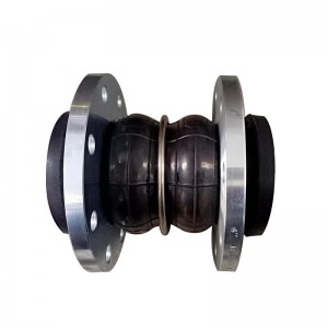
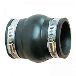
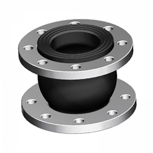
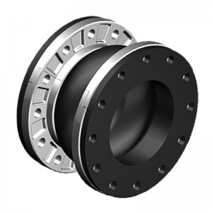
ODM Supplier China Customized Weather Proof Buna-N EPDM Rubber Elbow Tube
We’re proud with the high client fulfillment and wide acceptance due to our persistent pursuit of high quality both of those on products and service for ODM Supplier China Customized Weather Proof Buna-N EPDM Rubber Elbow Tube, With a quickly enhancement and our customers come from Europe, United States, Africa and everywhere in the world. Welcome to go to our manufacturing unit and welcome your get, for more inquires be sure to never hesitate to get in touch with us!
We’re proud with the high client fulfillment and wide acceptance due to our persistent pursuit of high quality both of those on products and service for China Rubber Elbow Tube, Rubber Elbow Pipe, We adopted technique and quality system management, based on “customer orientated, reputation first, mutual benefit, develop with joint efforts”, welcome friends to communicate and cooperate from all over the world.
Details
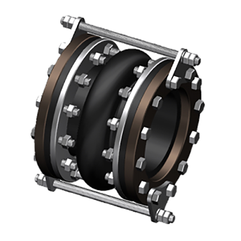
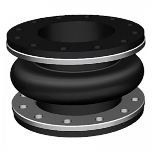
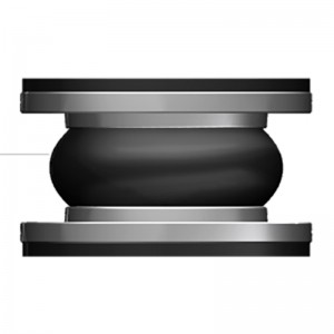
The spool type rubber joint is molded type, with a metal collar reinforced at the neck of the body. The ST stype uses a light reaining ring to support the integral flange. STF is filled arch, with 50% of the ST allowed movements, but it has 4 times spring rates than hollow arch.
| Specifications | I | II | III |
| Working Pressure Mpa (Kgf/Cm2) | 1Mpa (10) | 1.6 (16) | 2.5 (25) |
| Test Pressure | 1.5Mpa | 2.4Mpa | 3.75Mpa |
| Burst Pressure Mpa (Kgf/Cm2) | 3 (30) | 4.8 (48) | 5.5 (55) |
| Vacuum Kpa (Kgf/Cm2) | 53 (400) | 86(660) | 100 (750) |
| Materials | EPDM/NBR/SBR/NR | ||
| Diameter Range | DN15-DN600 (1/2″-24″) | ||
| Connection Method | FLANGETHREADCLAMP | ||
| Flanges Dimensions | DIN, EN,ANSI, BS, JIS and other standards | ||
| Applicable Medium | Air, compressed air, water, seawater, hot water, oil, acid, alkali etc. | ||
| Loading Port: | Qingdao, China | ||
| Shipment Terms: | FOB, CFR, CIF | ||
| Production Capacity: | 50000 set | ||
| Payment Terms: | L/C, T/T, D/P | ||
| Connection: | Flange, Thread | ||
| Flange Material: | Carbon Steel, Stainless Steel | ||
| Period of Delivery | about 21 working days | ||
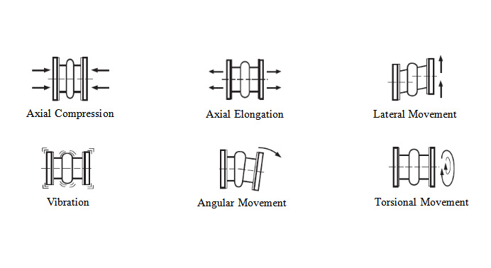
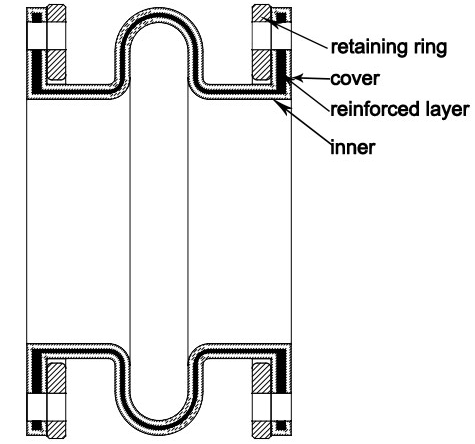
|
SPOOL TYPE (ST) -American Standard ST |
||||||||||
|
Dimensions |
Movement Distance |
Operating Condition |
||||||||
|
Pipe Size |
O’all Length |
Flange OD |
Retaining Ring Thickness |
Axial Compression |
Axial Extension |
Lateral Deflection |
Angular Deflection |
Max w.p. (psi)-3,-4 |
Max Vacuum (in. of Hg)-5 |
|
|
Inch |
mm |
Inch |
Inch |
Inch |
Inch |
Inch |
Inch |
|||
|
2″ |
50 |
6″ |
6″ |
3/8″ |
7/16″ |
1/4″ |
±1/2″ |
19° |
150 |
26 |
|
2 1/2″ |
65 |
6″ |
7″ |
3/8″ |
7/16″ |
1/4″ |
±1/2″ |
15° |
150 |
26 |
|
3″ |
80 |
6″ |
7 1/2″ |
3/8″ |
7/16″ |
1/4″ |
±1/2″ |
13° |
150 |
26 |
|
4″ |
100 |
6″ |
9″ |
3/8″ |
7/16″ |
1/4″ |
±1/2″ |
10° |
150 |
26 |
|
5″ |
125 |
6″ |
10″ |
3/8″ |
7/16″ |
1/4″ |
±1/2″ |
8° |
150 |
26 |
|
6″ |
150 |
6″ |
11″ |
3/8″ |
7/16″ |
1/4″ |
±1/2″ |
6° |
150 |
26 |
|
8″ |
200 |
6″ |
13 1/2″ |
3/8″ |
11/16″ |
3/8″ |
±1/2″ |
6° |
150 |
26 |
|
10″ |
250 |
8″ |
16″ |
3/8″ |
11/16″ |
3/8″ |
±1/2″ |
5° |
150 |
26 |
|
12″ |
300 |
8″ |
19″ |
3/8″ |
11/16″ |
3/8″ |
±1/2″ |
5° |
150 |
26 |
|
14″ |
350 |
8″ |
21″ |
3/8″ |
11/16″ |
3/8″ |
±1/2″ |
4° |
150 |
15 |
|
16″ |
400 |
8″ |
23 1/2″ |
3/8″ |
11/16″ |
3/8″ |
±1/2″ |
4° |
150 |
15 |
|
18″ |
450 |
8″ |
25″ |
3/8″ |
11/16″ |
3/8″ |
±1/2″ |
3° |
150 |
15 |
|
20″ |
500 |
8″ |
27 1/2″ |
3/8″ |
13/16″ |
7/16″ |
±1/2″ |
3° |
150 |
15 |
|
24″ |
600 |
10″ |
32″ |
3/8″ |
13/16″ |
7/16″ |
±1/2″ |
3° |
150 |
15 |
|
SPOOL TYPE: FILLED ARCH (STF) -American Standard STF |
||||||||||
|
Dimensions |
Movement Distance |
Operating Condition |
||||||||
|
Pipe Size |
O’all Length |
Flange OD |
Retaining Ring Thickness |
Axial Compression |
Axial Extension |
Lateral Deflection |
Angular Deflection |
Max w.p. (psi)-3,-4 |
Max Vacuum (in. of Hg)-5 |
|
|
Inch |
mm |
Inch |
Inch |
Inch |
Inch |
Inch |
Inch |
|||
|
2″ |
50 |
6″ |
6″ |
3/8″ |
7/32″ |
1/8″ |
±1/4″ |
9.5° |
150 |
26 |
|
2 1/2″ |
65 |
6″ |
7″ |
3/8″ |
7/32″ |
1/8″ |
±1/4″ |
7.5° |
150 |
26 |
|
3″ |
80 |
6″ |
7 1/2″ |
3/8″ |
7/32″ |
1/8″ |
±1/4″ |
6.5° |
150 |
26 |
|
4″ |
100 |
6″ |
9″ |
3/8″ |
7/32″ |
1/8″ |
±1/4″ |
5° |
150 |
26 |
|
5″ |
125 |
6″ |
10″ |
3/8″ |
7/32″ |
1/8″ |
±1/4″ |
4° |
150 |
26 |
|
6″ |
150 |
6″ |
11″ |
3/8″ |
7/32″ |
1/8″ |
±1/4″ |
3° |
150 |
26 |
|
8″ |
200 |
6″ |
13 1/2″ |
3/8″ |
11/32″ |
3/16″ |
±1/4″ |
3° |
150 |
26 |
|
10″ |
250 |
8″ |
16″ |
3/8″ |
11/32″ |
3/16″ |
±1/4″ |
2.5° |
150 |
26 |
|
12″ |
300 |
8″ |
19″ |
3/8″ |
11/32″ |
3/16″ |
±1/4″ |
2.5° |
150 |
26 |
|
14″ |
350 |
8″ |
21″ |
3/8″ |
11/32″ |
3/16″ |
±1/4″ |
2° |
150 |
15 |
|
16″ |
400 |
8″ |
23 1/2″ |
3/8″ |
11/32″ |
3/16″ |
±1/4″ |
2° |
150 |
15 |
|
18″ |
450 |
8″ |
25″ |
3/8″ |
11/32″ |
3/16″ |
±1/4″ |
1.5° |
150 |
15 |
|
20″ |
500 |
8″ |
27 1/2″ |
3/8″ |
13/32″ |
7/32″ |
±1/4″ |
1.5° |
150 |
15 |
|
24″ |
600 |
10″ |
32″ |
3/8″ |
13/32″ |
7/32″ |
±1/4″ |
1.5° |
150 |
15 |
Products categories
-

Phone
-

E-mail
-

Whatsapp
whatsapp

-

WeChat
Jessy Lin

-

WeChat
Ellen Zhang


